

What Causes Overheating in 400V and 800V EV High-Voltage Wiring Harnesses?
Overheating in an EV high-voltage wiring harness can melt connector housings, damage insulation, trigger isolation faults, shut down the vehicle, or lead to a costly safety recall.
The most effective solution is to control current density, contact resistance, cable routing, terminal processing, and environmental exposure as one complete high-voltage system.
Although 800V platforms can reduce current for the same power level, poor crimps and high-resistance interfaces can still create dangerous local hot spots.
For battery projects requiring customized conductor size, cable length, shielding, connectors, and HVIL integration, review our manufacturing options.
custom 800V EV high-voltage wiring harness
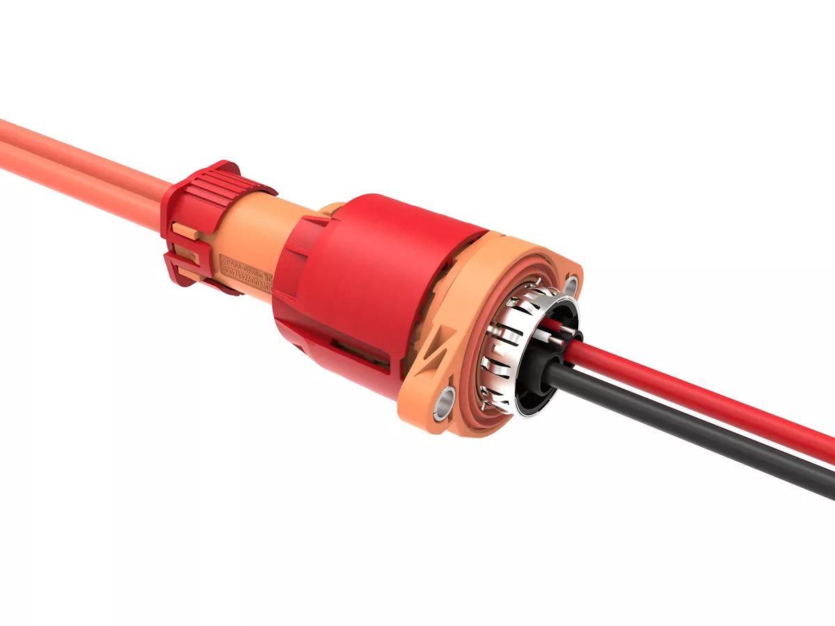
Molex
.[4]
Why Do 400V and 800V Harnesses Overheat Differently?
A 400V harness carrying high traction or charging power may require more current, increasing conductor, terminal, and connector heat when the cable size or cooling margin is insufficient.
The solution is to calculate cable and terminal capacity from real continuous current, peak current, ambient temperature, duty cycle, bundling, and cooling conditions.
At the same power level, an 800V architecture can operate at roughly half the current of a 400V system, reducing resistive losses when conductor resistance remains unchanged.
However, 800V does not automatically mean a cool wiring harness.
Fast charging can still involve several hundred amperes, while every crimp, weld, terminal, busbar, and connector interface introduces resistance and heat. Aptiv notes that higher charging currents increase heat generation and make interface resistance a critical reliability factor.[1]
Which Design and Assembly Faults Create Hot Spots?
An incorrectly sized cable, weak crimp, loose terminal, incomplete connector mating, damaged conductor, or contaminated contact can concentrate heat in one small area until the insulation or housing fails.
The correct solution is to control every electrical interface from conductor preparation to final connector locking.
Crimp height, conductor insertion, weld quality, terminal retention, contact resistance, cable bend radius, clip spacing, and sealing must be verified during production.
| Overheating Cause | Possible Consequence | Recommended Control |
|---|---|---|
| Undersized conductor | Excessive cable temperature and voltage drop | Current derating and thermal simulation |
| High-resistance crimp or weld | Localized terminal hot spot | Crimp-force monitoring and resistance testing |
| Incomplete connector mating | Contact heating, arcing, or power interruption | CPA, HVIL, locking, and visual inspection |
| Water or salt ingress | Corrosion and rising contact resistance | Seal validation and assembled-harness leak testing |
| Excessive bending or vibration | Broken strands and reduced conductor area | Controlled bend radius, clips, and strain relief |
High ambient temperature, tightly bundled cables, poor airflow, and nearby inverters or motors can reduce the harness current-carrying capacity.
Catalog ratings must not be applied without checking the actual cable size, installation temperature, routing, and operating cycle.
How Should Overheating Be Prevented and Tested?
A harness that passes continuity inspection at room temperature may still overheat during fast charging, hill climbing, thermal cycling, vibration, or long-term corrosion exposure.
The solution is to measure temperature rise and electrical resistance on the complete harness under representative vehicle conditions.
ZVEI guidance includes conductor resistance, current-carrying capacity, short-circuit strength, sealing, mechanical stability, and system-level harness validation.[2]
Recommended checks include voltage drop, millivolt-drop testing, conductor resistance, terminal temperature rise, thermal imaging, insulation resistance, dielectric withstand, vibration, thermal shock, fluid exposure, and repeated high-current cycling. ISO 19642-2 provides automotive cable test methods that support cable and harness qualification.[3]
Temperature sensors and software protection can detect abnormal heating, but they cannot correct an undersized cable or defective crimp.
The root cause must be removed through conductor sizing, low-resistance interfaces, controlled assembly, and validated routing.
Send your maximum voltage, continuous and peak current, conductor size, connector model, cable length, shielding requirement, routing drawing, and temperature-rise data for an engineering review.
FAQ
Does an 800V EV wiring harness generate less heat than a 400V harness?
It can generate less conductor heat at the same power because the current may be lower. Connector resistance, charging current, temperature, and routing still determine the actual result.
What is the most common cause of high-voltage connector overheating?
High contact resistance caused by poor crimping, incomplete mating, contamination, corrosion, or reduced terminal contact force is a common cause.
Can an oversized cable prevent all overheating?
No. A larger cable cannot eliminate heat caused by a defective terminal, poor weld, loose connection, damaged seal, or incorrect connector rating.
How is EV high-voltage harness overheating detected?
Engineers use temperature-rise testing, thermal imaging, voltage-drop measurement, contact-resistance testing, onboard sensors, and diagnostic software.
Based on 15 years of automotive wire harness experience, I do not judge overheating risk from voltage or cable size alone. The real answer is found by reviewing the conductor, crimp, weld, terminal, connector, seal, routing, current profile, and ambient temperature as one complete 400V or 800V system.


